Making a Kempston compatible joystick interface

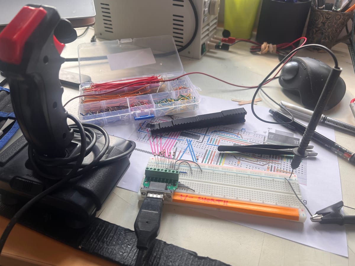
In this post, we'll make our own version of the Kempston joystick interface that I described in part 1. We'll make a slight modification: full address decoding, to avoid any future resource conflicts.
We'll keep the 74HC138N (3-to-8 decoder) for decoding the control signals, but we'll swap out the 74LS366 for a 74HC240N - this is an octal inverting buffer, rather than a hex inverting buffer: in other words we've got 8 inverters to match our 8 data lines.
We're also going to add a new chip, that's going to be in charge of the full address decode: a 74HC688N 8-bit magnitude comparator. This chip has two sets of 8-bit binary inputs, and an output that's active when they're equal. So if we wire one 8-bit wide input to our address lines A[7:0] we can set up the other input to represent the IO port address we want to live at (let's use 0x1f [31] for compatibility's sake). Then we pass the output to the 74HC138N.
Here's a mockup in Fritzing of what we'll be building:
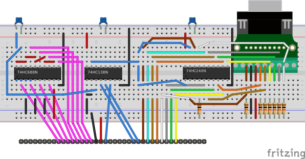
It's always worth mocking up a breadboard in Fritzing to ensure that everything fits and you're not going to run out of space. It's infuriating to use, but nowhere near as bad as ripping out and replacing a load of wires on an actual breadboard. I like to print out the final graphic and use it as a guide to assembling the real thing.
Joystick input
Let's start with the joystick input. DB9 shells are a bit of a pain to work with, but I found these handy little adaptoids that make them amenable to breadboarding. You just need to solder in a pin header across the middlle and it plonks straight into the breadboard.
I wired up the DB9 connections so that I could test them:
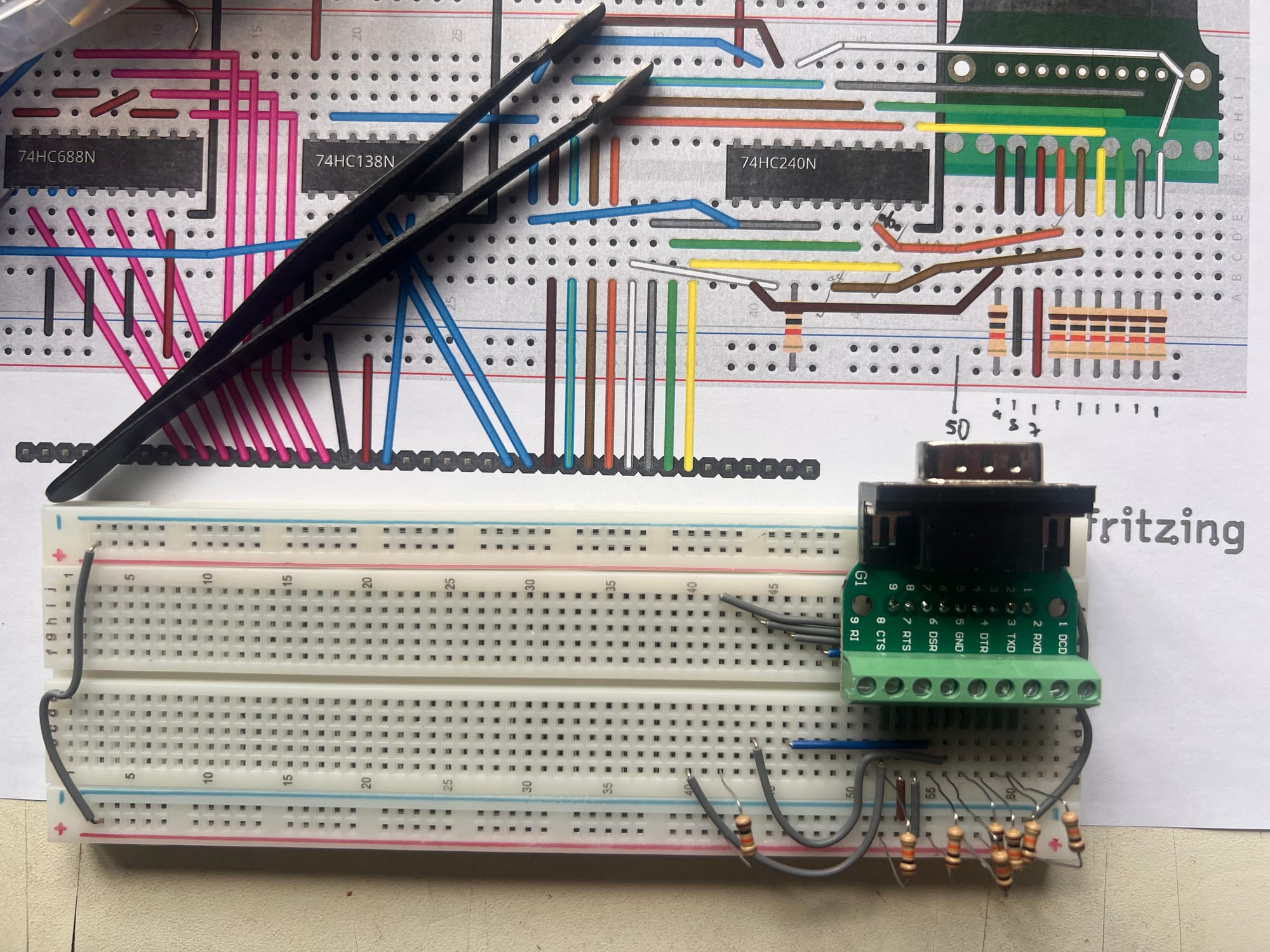
I left my resistors long-legged, which is not a very good idea and runs the risk of a short. It does mean I can put them back in the parts bin afterwards though! If you're following along I advise you to cut yours to fit.
I'm using a knackered old Quickshot II from eBay, which certainly smells vintage. I put a multimeter in continuity mode across the common pin and each of the switch pins, and pressed fire or moved the stick to make sure I got a beep.
This got me four working directions but neither fire button was responding, so I opened up the Quickshot II, gave it a good clean, checked the connections, applied some switch lube, put it back together, and everything worked great.
You might notice in the video and the masthead image that I've got some orange tape over one of the supply rails. This is because those two rails are shorted together: a common and deeply unamusing failure mode of cheap and nasty breadboards, which most contemporary ones seem to be (even if you bought them somewhere posh, like the Cambridge Raspberry Pi store, ahem).
What I should have done was test for that as soon as I opened the packet. Sometimes you can fix it by taking the sticky foam off the back and giving it a good fettling. But unfortunately I'd already mounted a load of stuff on the board, so it's easier just to tape the whole thing off and use the one remaining pair of rails.
Octal inverter
Now that we're happy with our joystick, DB9 connector and associated wiring, we can add our octal inverter, and test the outputs from that as we waggle the stick. Remember the stick is pulling things low, so we ought to see signals going high on the outputs of the inverter.
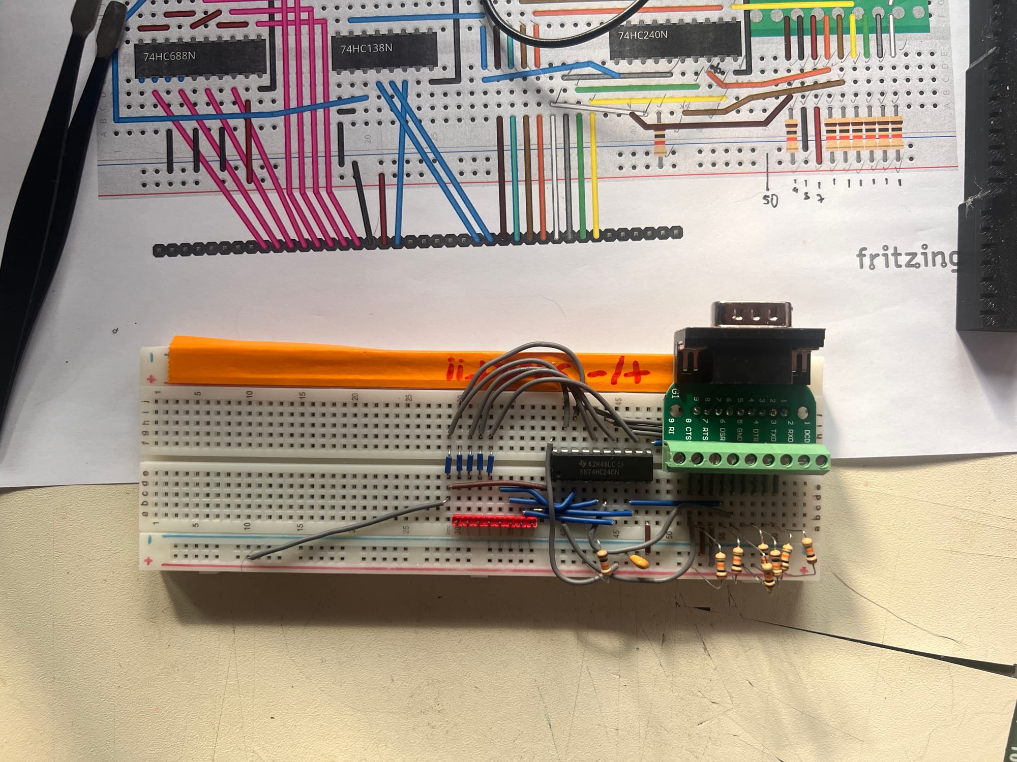
That long grey wire bottom right gives me a manual way to control the output enables of the 74HC240N octal inverter, by connecting it to +5v (disabled) or 0v (enabled). In the video I've hooked up an LED and a 330 ohm resistor as a simple test indicator that will light when whatever signal it's plugged into goes high.
Control bus decoding
Let's get our 74HC138N on the board and decode the control bus signals. We've got pins 4 and 5 (G̅2A and G̅2B respectively) connected to I̅O̅R̅E̅Q̅ and R̅D̅ because we're interested in when those signals are low, and we've got pin 6 (G1) connected to M̅1̅ because we're interested when that signal is high. For the time being I've set the inputs A, B and C low.
In the video below you can see that LED is lit when I̅O̅R̅E̅Q̅ and R̅D̅ are low, M̅1̅ is high, A, B and C are low. I mess about trying various other combinations to demonstrate that the LED goes out.
Address bus decoding
As we've already seen, the original Kempston joystick does a partial decode of three of the address bus lines, corresponding to the available A, B and C inputs on the 74HC138N. We're going to tie two of those inputs permanently low, and drive the remaining input from a 74HC688N 8-bit magnitude comparator, so we can do a full IO address decode, which will make us a better citizen.
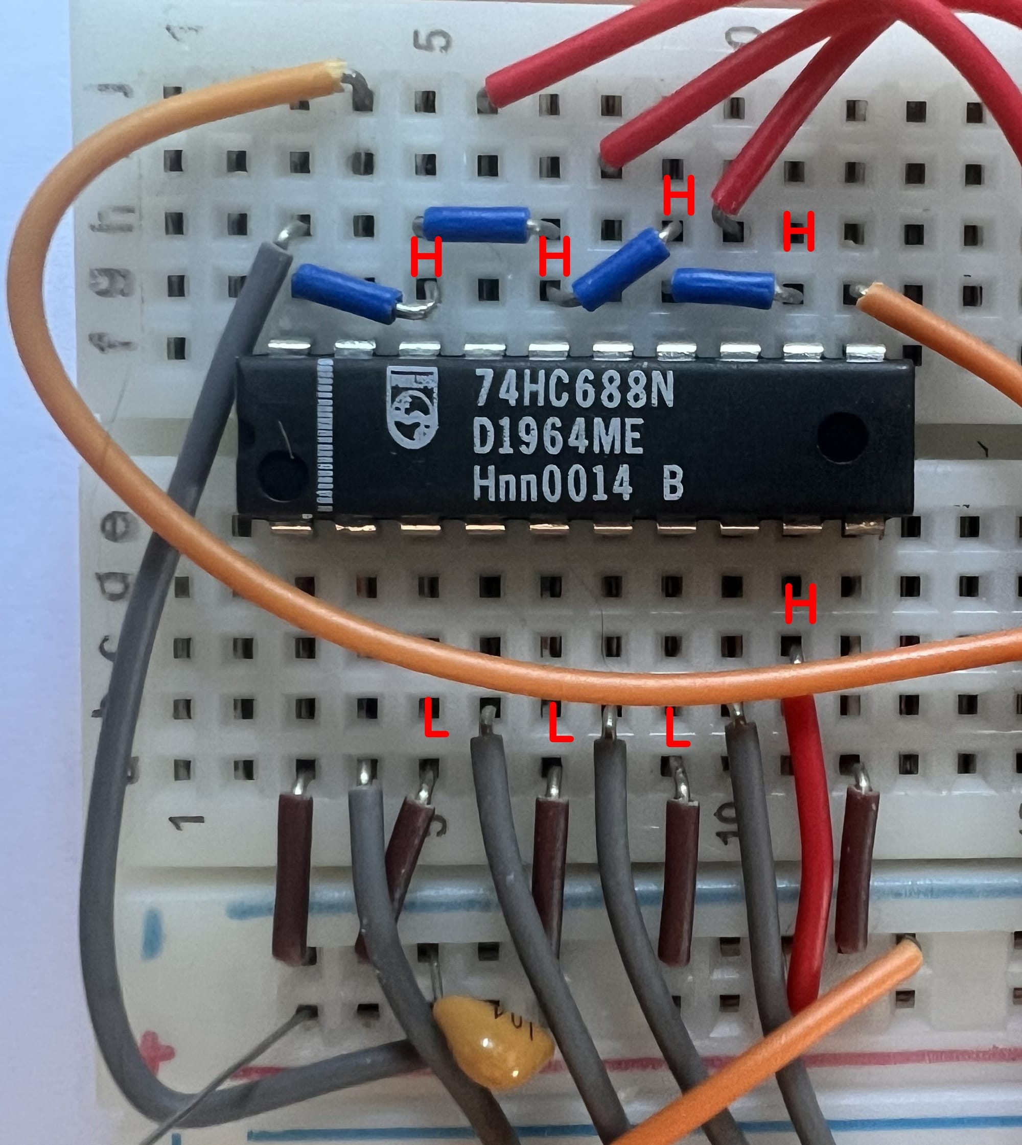
We'll put in some wire links so we can configure the IO address that we'd like the joystick interface to respond to. In our case, from A7 down to A0 this will be LOW, LOW, LOW; HIGH, HIGH, HIGH, HIGH, HIGH - corresponding to port 1Fh or 31 decimal, the same as the Kempston joystick.
In the video I move the debug LED to the output of the 74HC138N, and demonstrate that changing a single bit of the IO port address causes the LED to go out.
Our Kempston-compatible joystick interface prototype is working on the bench: join me in part 3 where we hook it up to a MicroBeast and attempt to read it from software.

Comments