Make a PCB for the Kempston joystick interface

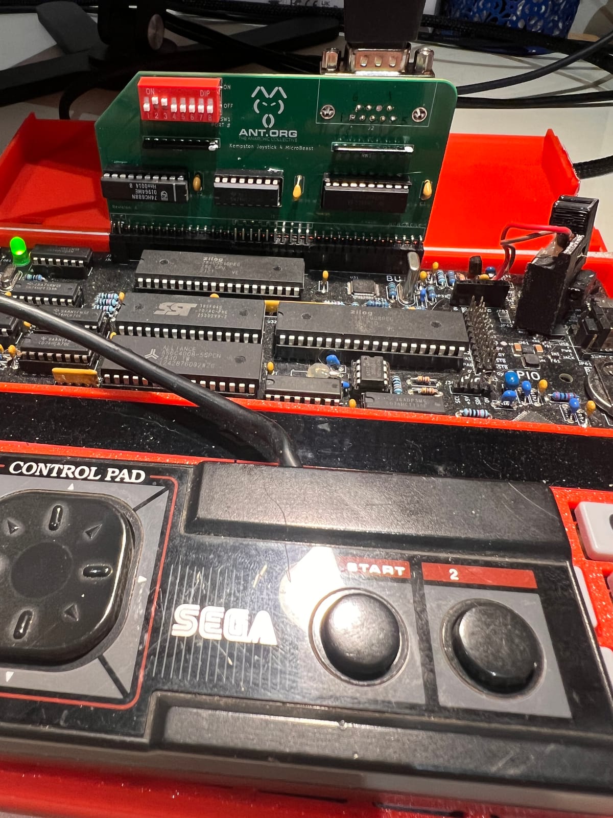
The joystick interface we played with in Testing the Kempston compatible joystick interface works beautifully, but it is somewhat delicate. Even moving the MicroBeast a couple of feet or so runs the risk of connecting wires becoming dislodged, and those absurd flying resistors need the flimsiest of excuses to short each other out.
What we need is a more rugged, permanent solution. The easiest way to do that is to build a PCB. I'll be using the excellent open-source Kicad package (version 10).
Designing the schematic
The first stage is "Schematic capture", or drawing the circuit diagram. We can pretty much trace this off the wiring diagram from the breadboard. A real time saver is the ability to use net names: you don't need to draw an actual wire between two pins if you gave them the same net name: A0 on connector J2 is implicitly connected to pin 3 on U1 for example.
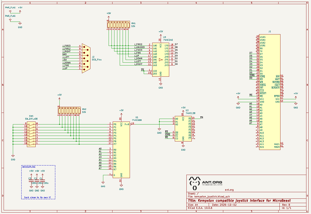
I've taken the opportunity to add the bank of 8 DIP switches for setting the port address, and we're using nifty "resistor networks" instead of individual resistors.
Thinking about board layout
Since this is an RC2014 style expansion card, we'll base our layout on the RC2014 module template:
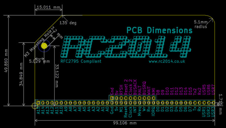
One thing to watch out for: this template restricts the width to 100mm, because that's often a cost breakpoint at some PCB manufacturers, and also because another (older) popular PCB design program Eagle was limited to 100mm in its free version. Limiting the width to 100mm has the effect of clipping off the last pin on the right hand side (it would have been USR4 in the diagram).
Neither Kicad nor our chosen board manufacturer have these restrictions, so we'll go slightly wider and reinstate that pin.
Enhanced RC2014
The original RC2014 bus module had a single row of 40 pins, but there's an enhanced bus specification that adds a second row of up to an additional 40 pins:
| Pin | Label | Description | Note |
|---|---|---|---|
| 1-16 | Not used | ||
| 17 | Gnd | 0v power supply | |
| 18 | 5v | 5v power supply | |
| 19 | RFSH | M1 control line from CPU | Active Low |
| 20 | Reset2/Page | Secondary reset or page line for other modules | Active Low |
| 21 | Clock2 | Secondary clock line for other modules | |
| 22 | BUSACK | Bus Acknowledge | Active Low |
| 23 | HALT | Halt | Active Low |
| 24 | BUSRQ | Bus Request | Active Low |
| 25 | WAIT | Wait | Active Low |
| 26 | NMI | Non-maskable Interupt | Active Low |
| 27 – 34 | D8 -D15 | Additional 8 data lines (for 16bit CPU) | |
| 35 | Tx2 | Secondary serial transmit | |
| 36 | Rx2 | Secondary serial receive | |
| 37 – 39 | USR5-7 3 | spare pins for user functions | |
| 40 | USR8 | 4th spare pin. Suggest it is not used | Avoid |
The 10 pins in the centre of this new row (pins 17 to 26) should be considered "mandatory", while the rest are optional.
Note that the MicroBeast uses two of the "Not used pins" (Pin 1 and pin 2) to carry signals MA20 and MA21 from its "paged memory bus" allowing genuine Feersum peripherals to do simplified address decoding: the VideoBeast makes use of this facility.
Together these connectors are J31 ("RC2014 bus"), J35 ("Extended bus") and J36 ("Paged memory bus") in the MicroBeast schematic.
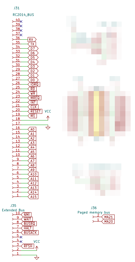
Note that the upcoming NanoBeast adds a third pin:
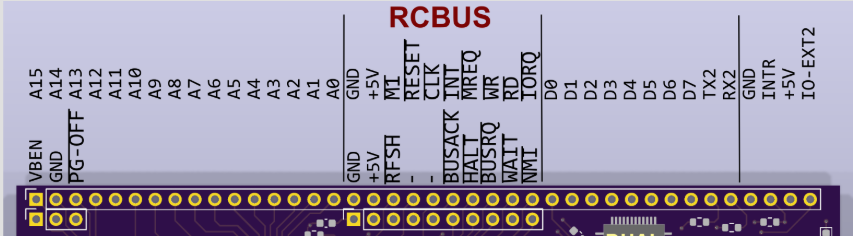
and it's also defined some of the former "USER" pins on the basic RC2014 header as GND, INTR, +5V, and IO-EXT2. "VBEN" is fairly obvious and it's the NanoBeast's equivalent to the MicroBeast's MA20. We can only speculate what the other signals are for!
I opted to layout my board like this:
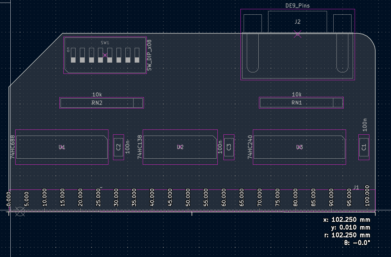
The DE-9 joystick connector and DIP switches for setting the port number are at the top so they're easily accessible. I'm slightly wider than the official RC2014 template at 102mm in order to accommodate the 40th pin.
PCB layout
With the initial placement done, all that remains is to route the PCB tracks. In the hands of a skilled professional this is as much art as it is science, and design engineers often take a great deal of pride in elegant, hand-routed layouts.
However, I'm a software engineer, and an impatient one at that, so I'm happy to let an autorouter take the strain, especially for a board this simple. In Kicad you have a couple of options, but I elected to use the newer KicadRoutingTools. It's a little bit terse, but there is plenty of documentation and YouTube coverage.
Here's what it came up with:
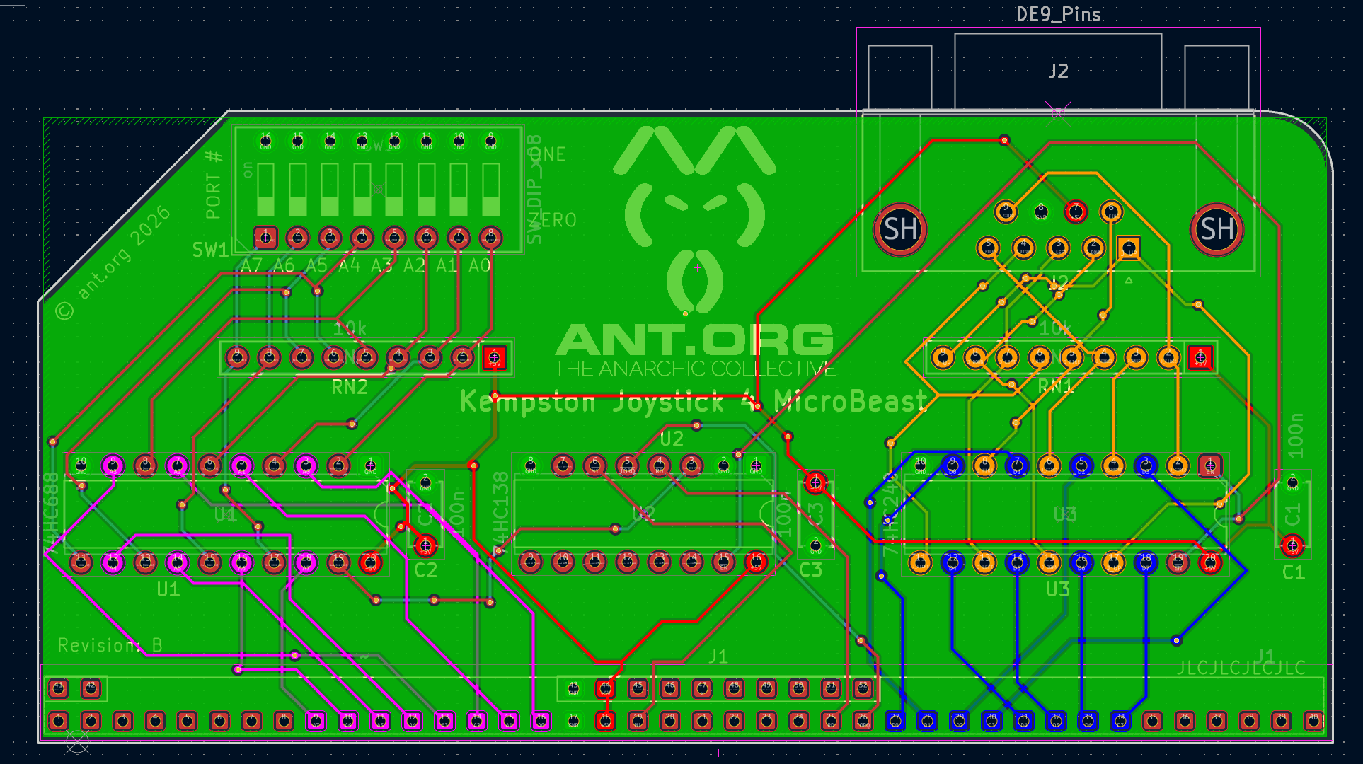
It's not the prettiest thing, and even I can see that the complicated business around the joystick port is a bit of a mess, put it passes DRC (Design Rules Check) so in theory it's good to go.
The next step is to have the little guy manufactured. For this i like to use JLCPCB, and the excellent "JLCPCB Tools" plugin for Kicad does all the work in generating the Gerber files that their website requires. Since these are all through-hole components I'll build the board at home mysself, so I don't need to send them a BOM file.
Using the cheapest low-frills options and slowest delivery I ordered 5 PCBs for $14. They took 8 days to arrive.
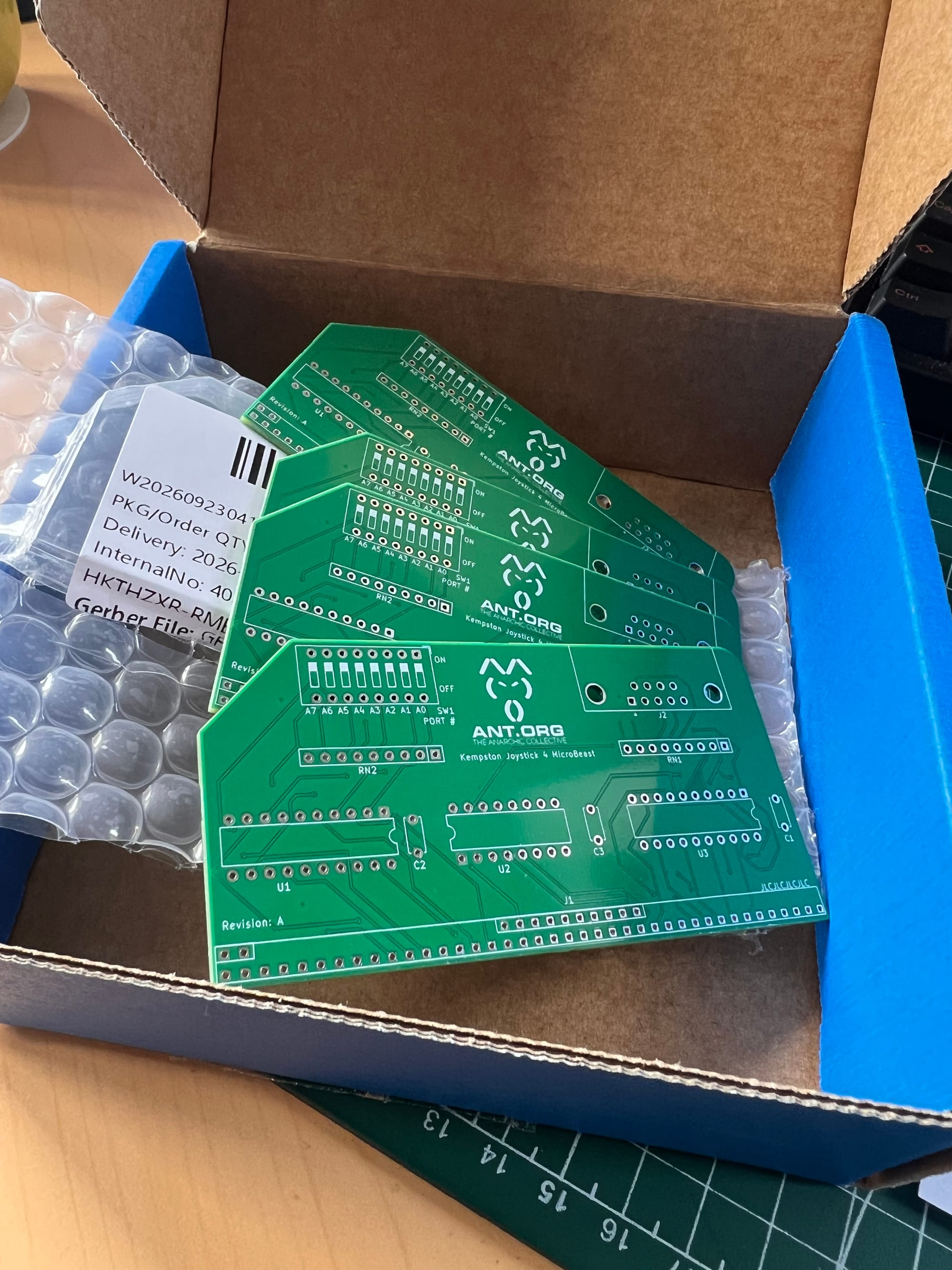
The board takes an hour or so to build up. I socketed all the ICs in case I want to harvest them for use in later projects.
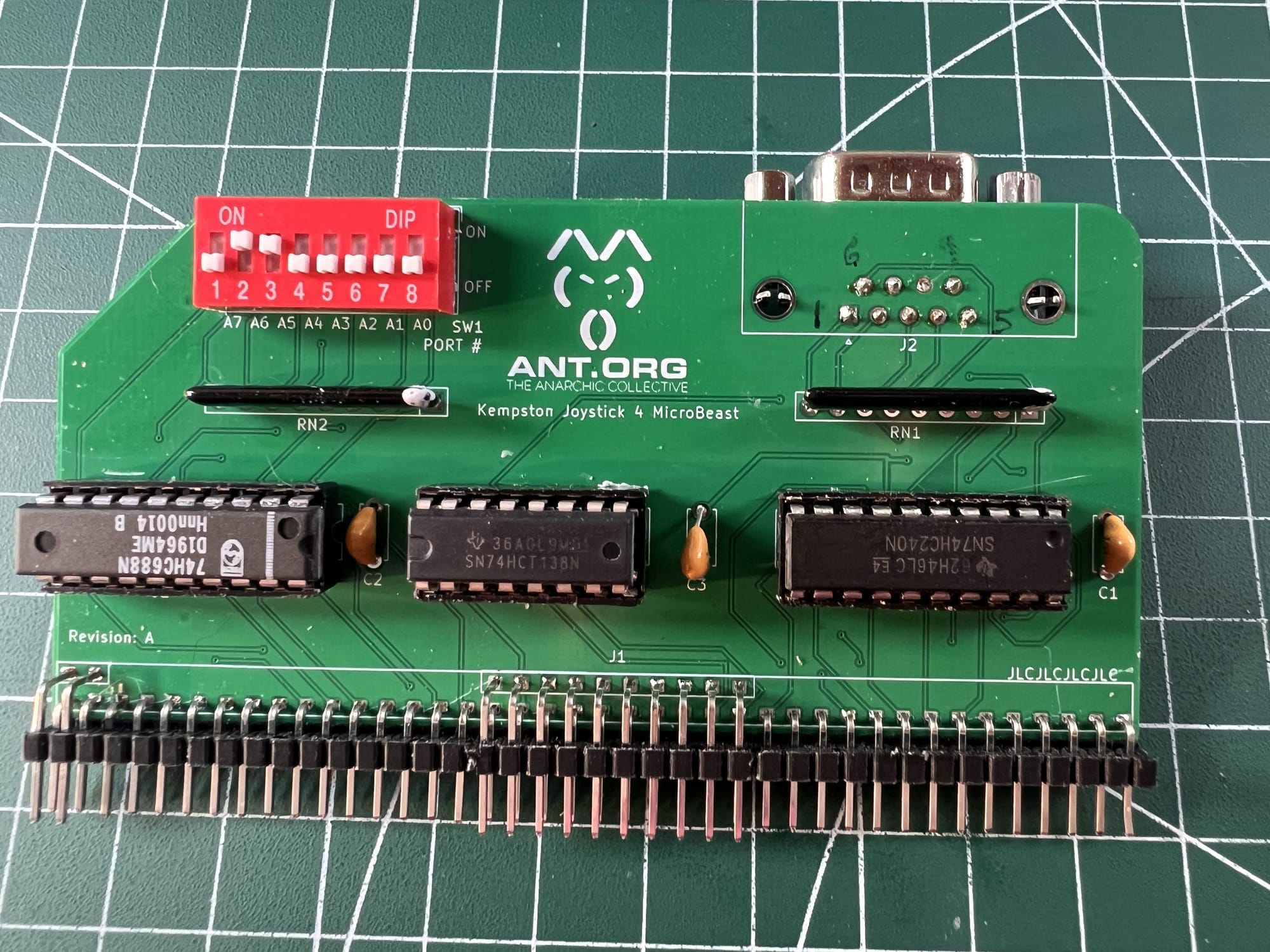
Eagle-eyed readers might notice a couple of discrepancies between these PCBs ("revision A") and the schematics/board loayouts shown above ("revision B"), and that's because I've since incorporated a couple of changes, notably:
- use the right DE-9 footprint, so that I don't have to mount the joystick connector on the wrong side of the board
- flip the orientation of U2 so that it points the same way as the other ICs
- invert the sense of the DIP switches so that it's more intuitive: in my picture the port number is to to 0x9f, because "ON" means "a zero in this bit position", which is a bit of a head scratcher.
Testing it out
We already developed all the test software in Testing the Kempston compatible joystick interface so I was able to quickly test this PCB and it worked first time! (OK, second time, once I'd desoldered the joystick connector and soldered it on the back of the board).
Build your own
If you'd like to make your own PCBs for this project, everything you need is in the github repo - specifically mpcbs/jlcpcb/production_files/GERBER-kempston-joystick.zip is the bundle you can upload to JLCPCB.
The full Kicad project is on there if you want to modify the design, or use it as a jumping off point for your own projects.
PCB giveaway
I made 5 rev A PCBs but I only need one, so I'll give the rest away to anyone that wants them - just pay the postage. Or for a small consideration (a tenner, say) I'll build the board for you and post it. Find me on the MicroBeast Discord server if you're interested!


Comments