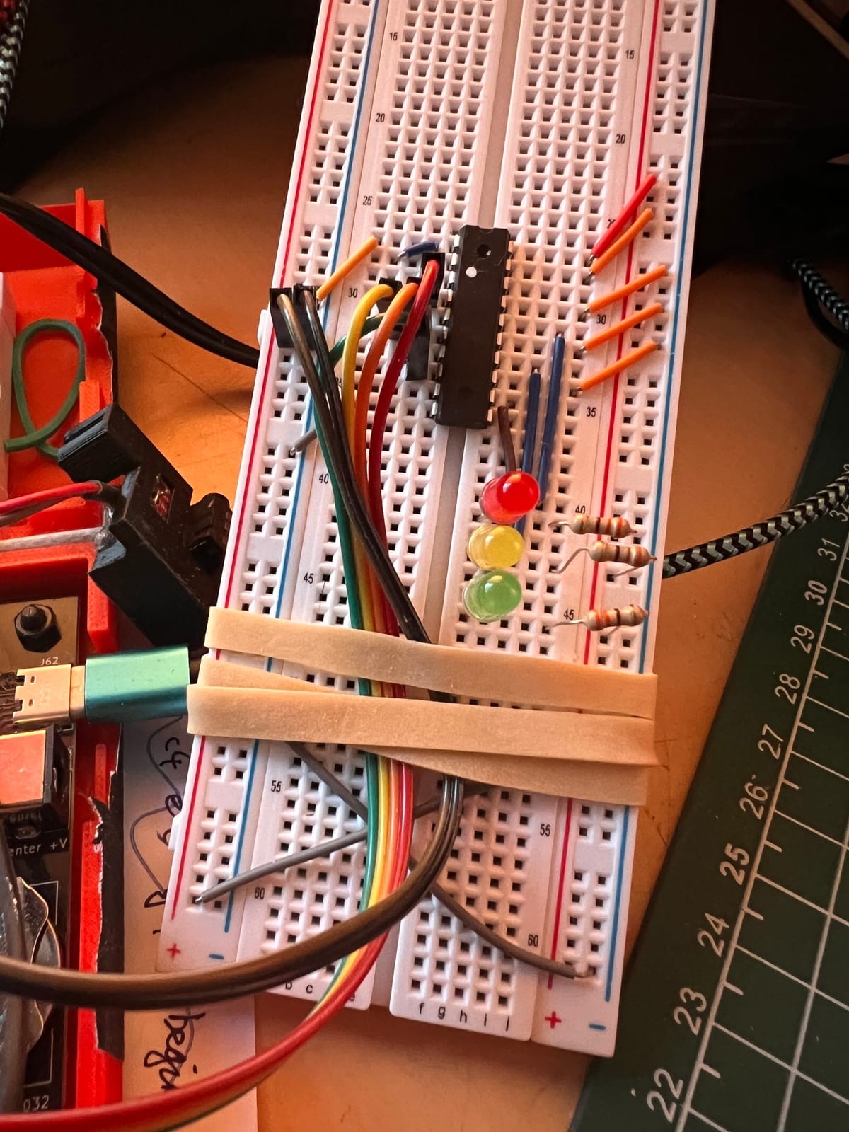
The MicroBeast and NanoBeast are extremely expandable computers - they offer a range of interfaces including GPIO, I2C, UART, and RC2014. These interfaces vary in their complexity and capabilities, ranging from turning a simple LED on and off all the way up to a full-blown graphics card.
We'll be taking a look at the PIO interface, and using it to control 3 LEDs arranged in the standard traffic light pattern of red, amber, and green. We'll write some code to turn the LEDs on and off, and then we'll concentrate on sequencing them so they behave like a real traffic light.
GPIO interface
The interface I've chosen for this project is the 'Beast's GPIO (General Purpose Input/Output). This is a digital interface: we can either read a signal to see if it's HIGH (5 volts) or LOW (0 volts), or we can turn things around and drive a signal either HIGH or LOW, to control something in the outside world (like an LED).
The 'Beast's GPIO interface is split into two halves called "Port A" and "Port B". Each of these has 8 "lines" (or "pins", or "signals") that we can use for whatever we want...well almost: the 'Beast is already using some of the Port B pins itself to interface with the I2C bus, the real time clock, and the UART. To keep things simple, we'll restrict ourselves to using Port A.
The Z84C20
The Z80 CPU launched with a companion chip, the Z80 PIO:
The Z8O Parallel I/O (PlO) Circuit is a programmable, two port device which provides a TTL compatible interface between peripheral devices and the Z80-GPU. The CPU can configure the Z8O-PIO to interface with a wide range of peripheral devices with no other external logic required, Typical peripheral devices that are fully compatible with the Z80-PIO include most keyboards, paper tape readers and punches, printers, PROM programmers, etc.
This integrates so well with the Z80 (particularly in the arena of interrupts) that it is still a popular choice with system designers. The MicroBeast includes a Z84C20, the modern variant. Here's the datasheet, and here's a handy user manual.
The NanoBeast has a different chip that we'll cover another time, but it is broadly compatible [1].
I think - not had a chance to play with one yet. ↩︎
We can treat the Z84C20 as a container for two ports which are (almost) identical. Each port has some registers that allow us to control it: that's a specific set of addresses in the Z80 CPU's I/O address space that allow us to control the Z84C20. These are:
- a CONTROL register, that configure the port, including setting its mode, which pins are inputs and which outputs, and which pins generate an interrupt on change.
- a DATA register that lets us read or write the 8 signals that this port owns.
Port modes
Each port supports 4 different modes, they are:
- mode 0: output a byte at a time
- mode 1: input a byte at a time
- mode 2: input/output a byte at a team (steals some signals from Port B, so this is only available on Port A)
- mode 3: bit control mode
We'll be using mode 3, as we want individual control of 3 different LEDs, and this mode is the easiest way to achieve it.
Traffic light circuit
Let's get started on the hardware! First of all we're going to need a bit of breadboard, some LEDs and resistors, lots of precut wire links / bits of wire, and some hookup wires with 0.1" female headers for connection to the MicroBeast. We'll also need an integrated circuit, a 74HC244.
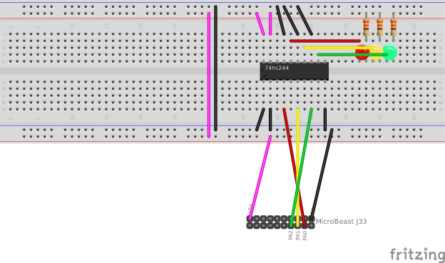
Here's an overview of what we'll be building:
First off we'll need some LEDs of the appropriate colours. I raided the parts drawer and came up with three likely candidates of dubious provenance. Measuring them with a multimeter I found the voltage drop across my red LED was 1.7v, the yellow LED was 1.8v, and the green LED was 2 volts.
We want to limit the current through these LEDs to about 10mA (plenty bright enoufg for our purposes), so we'll need a resistor for each LED. We can calculate the resistor value with the formula R = (Vcc - Vf) / If where Vf is about 2 volts (as measured), Vcc is 5V and If is 10 mA. This gives a value of 300 ohms. I don't have any 300 ohm resistors, but I do have 330 Ω, and pllugging that back in to the formula reveals that that gives an If of 9 mA, which is absolutely fine.
You might be wondering why we don't wire the LEDs directly to the 'Beast's PIO output: the Z84C20 can neither source (provide) nor sink (accept) 9mA - in fact it can only source 1.6 mA and sink 2mA, which is rather puny.
This is the reason for the 74HC244 IC in our circuit.
74HC244 3-state octal buffer and line driver
This is a package of 8 (hence "octal") "buffer"s, where a buffer is a device that has one input and one output, and the output's value follows the input. This might sound a bit pointless, but the buffer also isolates the input from the output, and provides a significant current boost.
In the case of 74HC2444, each pin can sink or source 35mA, with the proviso that the total current handled by the chip cannot exceed 70mA. So our 3 * 9 mA = 27 mA total is not going to cause the 74HC244 to break a sweat, even though it would give the Z84C20 a bit of a migraine.
Just to be safe, we're using the 74HC244 to sink current rather than sourcing it: this means that current flows from the power supply, through the LED and resistor, and is delivered into the 74HC244. This has the consequence of inverting the control logic (we drive a line LOW to light the LED) - more on this later.
You can buy 74HC244s from all the usual component suppliers, but they are often expensive in small quantities. eBay or AliExpress are a much cheaper option if you can wait for a few days, but beware fakes and duds. I bought 10 from AliExpress and they all checked out fine. If you're really desperate, get hold of me on Discord and I'll send you one.
Our RED led is wired to the 'Beast's PA0 pin, the amber LED to PA1, and the green PIN to PA2:
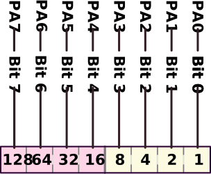
This means writing the value 0x01 to Port A's data port will control the red LED, the value 0x02 will control the amber LED, and the value 0x04 will control the green LED.
If that leaves you a bit mystified, you could try our introduction to binary and hex.
Here's my board for reference:
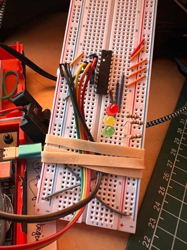
The rubber band is there to provide "strain relief", i.e. stop the Dupont pins pulling out of the board when you move the cables.
Don't forget to connect your power rails together (as in, connect the top + rail to the bottom + rail, and connect the top - rail to the bottom - rail) – do not connect a + rail to a - rail! In the Fritzing diagram this is shown as a long pink wire and a long black wire across the centre of the board. In the photo above, it's the two X shaped grey wires at the bottom.
Also worth noting that your LEDs, being diodes, need to go in the right way round. If you fit them in reverse, they won't work. An LEDs terminals are called the "cathode" and the "anode". Current must enter the LED at the anode and leave via the cathode. The cathode is usually marked by a slight flattening on the LED housing, and it usually has a shorted lead than the anode. If in doubt, test with a multimeter first.
I'll leave you to go have fun building the circuit. In part 2, we'll write some simple code to drive it!
Build a traffic light!
The MicroBeast and NanoBeast are extremely expandable computers - they offer a range of interfaces including GPIO, I2C, UART, and RC2014. These interfaces vary in their complexity and capabilities, ranging from turning a simple LED on and off all the way up to a full-blown graphics card. We'll


